PRECISION PROFILES / Laser Cutting
Your drawing. A clearer path to cut parts.
Turn two-dimensional profiles into a well-defined cutting scope. For prototypes and production parts, consistent units, revisions and edge requirements help avoid ambiguity.
01 / THE PROCESS
Start with the application.
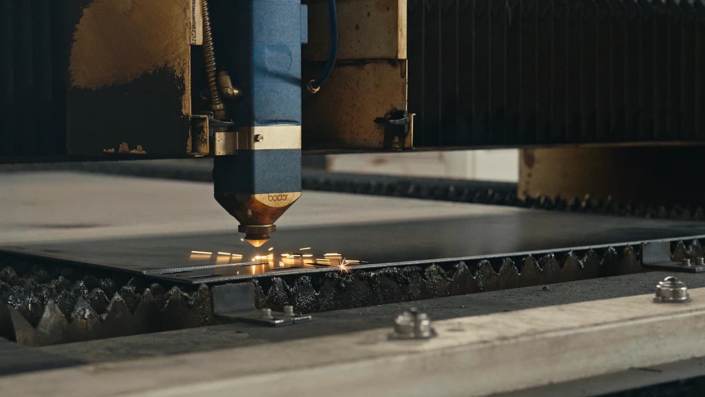
Laser cutting uses a focused beam and process gas to separate material along a programmed profile. Suitability depends on the material, thickness, geometry and required edge condition rather than a universal capability figure.
A cut part may still need deburring, tapping, machining, bending or coating. Identify those operations early so small features, heat effects and edge requirements can be evaluated in the context of the finished component.
02 / APPLICATIONS
Typical fabrication applications.
Potential project types to help define your scope.
Sheet profiles
Flat outlines for panels, covers and components with defined edge conditions.
Plate components
Thicker profiles with material and downstream machining requirements identified.
Steel brackets and blanks
Profiles prepared for later forming, joining or mounting.
Stainless parts
Components with cosmetic faces, grain direction and corrosion requirements.
Aluminum components
Lightweight profiles with alloy, surface protection and finishing specified.
Prototypes
Initial cut parts for dimensional or fit review against a controlled revision.
Production parts
Repeated profiles with quantities, part identifiers and acceptance criteria.
Cut-to-drawing components
Custom geometries with a dimensioned reference and unambiguous units.
03 / MATERIAL SELECTION
Choose for the working environment.
Material suitability and availability are reviewed against your specification.
Steel sheet and plate
Specify grade and thickness, plus any coating or downstream weld requirements.
Stainless steel
Identify grade, visible faces and edge treatment. Process gas and subsequent cleaning can affect edge condition.
Aluminum
Specify alloy and thickness. Feature size, edge quality and any further forming need review.
04 / FABRICATION CAPABILITIES
Connect the processes.
File preparation
Provide closed profiles without duplicated lines, an explicit unit system and a dimensioned reference. Agree suitable file formats during quotation.
Nesting & part orientation
Quantities and sheet utilization affect layout. Grain direction, cosmetic faces and part identification can limit rotation or nesting choices.
Edge & feature review
Define acceptable burr, cut-edge condition and critical holes. Some holes or interfaces may need a secondary operation rather than relying on the cut edge alone.
05 / INDUSTRIES SERVED
Built around your sector.
06 / PROJECT REQUIREMENTS
A better brief.
A clearer quote.
List each part number, drawing revision, material, thickness and quantity. Include units, critical dimensions, grain direction and all required secondary operations.
Add supported drawings in the secure document step when upload is available. You can also submit the scope without files and identify what needs clarification.
PREPARE YOUR RFQ ↗Drawings & specifications
Identify the revision, units, intended use and critical dimensions. Describe available drawings in your inquiry.
Material & quantities
State material preferences, thickness or section, part quantities and repeat-order expectations.
Finish & acceptance
Define finish, visible faces, dimensional requirements, inspection and documentation.
Delivery & schedule
Include city, province, access or unloading constraints and the required project dates.
Installation & interfaces
Identify site work, mating components, measurement responsibilities and installation needs where applicable.
QUESTIONS / ANSWERS
Before you specify.
What files should I prepare?
Prepare a clean vector profile such as DXF or DWG alongside a dimensioned PDF reference. Keep units, part numbers and revisions consistent. The secure document step accepts supported drawings when upload is available; a request can also begin without files.
Should I add a kerf offset to my drawing?
Normally describe the required finished geometry and flag any existing compensation. Toolpath compensation should be agreed with the cutting process so it is not applied twice.
Are all small holes suitable for laser cutting?
No universal minimum applies across materials and thicknesses. Identify critical features so they can be reviewed for cutting or a secondary process.
Will the edge be ready for welding or coating?
That depends on material, process gas and the finish requirement. Specify whether deburring, oxide removal or another preparation step is required.
Can different parts be nested together?
List quantities, materials and orientation constraints. Nesting can improve material use, but mixed thicknesses, grain direction or protected faces may limit the layout.
MATERIAL / METHOD
Explore the fabrication decisions.
Relevant capabilities
Material guidance
CONNECTED PROCESSES
Complete the fabrication scope.
FOCUSED FABRICATION
Start with the component you need.
Explore specific metalwork requirements, from individual mounting parts to complete fabricated assemblies.
Custom Brackets & Plates
Define the connection before the component. Mounting brackets, adapter plates and gussets bring equipment, frames and building interfaces together when catalogue hardware does not suit the geometry.
EXPLORE REQUIREMENTS ↗YOUR NEXT STEP
Make the cut list quote-ready.
Start with part numbers, quantities, thicknesses and the edge requirements that matter to the finished assembly.