FABRICATION SPECIALTIES / EQUIPMENT FRAMES & SUPPORTS
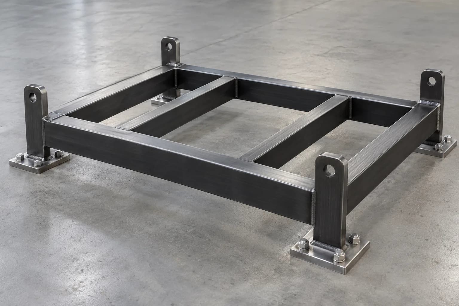
Equipment Frames & Supports: A defined base for the working assembly.
Plan equipment bases and support frames around real interfaces: mounting patterns, operating loads, service access and the floor or structure below. A clear design package connects fabrication to installation.
FUNCTION / FIT / FINISH
Define the part in its working context.
Equipment frames may be built from tube, sections and plate, with welded or bolted connections selected for the assembly. Provide the equipment layout and mounting references so component positions can be reviewed together rather than as isolated parts.
Operating loads can differ from transport or maintenance conditions. Identify vibration, eccentric loading and removable equipment. Design calculations, anchorage and any engineered lifting provisions require defined responsibility; they are not established by the size or appearance of a steel frame.
APPLICATIONS
Where the scope begins.
Equipment bases
Support frames with mounting plates and access openings coordinated with the equipment supplier.
Process support assemblies
Frames for project-specific components, with service routes, drainage and maintenance clearances identified.
Modular support structures
Bolt-together subassemblies where handling, doorway dimensions or phased installation influence the design.
DESIGN / PROCUREMENT
Resolve the details before fabrication.
Loads and stiffness
Provide static and operating loads, vibration information and alignment requirements. Identify the designer responsible for member sizes and connection details.
Mounting datums
Define critical elevations, flatness requirements and equipment hole patterns. State whether machining or leveling provisions form part of the scope.
Handling and installation
Provide delivery access, assembly sequence and anchorage requirements. Lifting points must be specifically designed and approved, not inferred from mounting tabs.
QUOTE PREPARATION
Prepare the frame package.
Assembly drawings
Include overall dimensions, section sizes, weld and bolt details, and a current bill of materials.
Operating environment
Identify indoor or outdoor exposure, cleaning chemicals, temperature and coating requirements.
Inspection and delivery
State dimensional checks, weld inspection, documentation and packaging requirements. Separate installation and equipment alignment from fabrication where appropriate.
Connect material and process.
Scope, material suitability, process availability and any inspection or installation commitments are confirmed through project review.
Material selection
Fabrication processes
CONNECTED PROCESSES
Complete the fabrication scope.
QUESTIONS / ANSWERS
Before you specify.
Can a frame be designed from equipment dimensions alone?
Dimensions are only part of the brief. Loads, stiffness, connections, foundation conditions and operating requirements must also be defined by the responsible designer.
Can the frame be delivered in sections?
Describe access restrictions and the intended assembly sequence. Bolted interfaces, handling and final alignment can then be reviewed as part of the scope.
Are lifting lugs included by default?
No. Handling and lifting provisions require an explicit design and approval process. Mounting holes and tabs must not be treated as lifting points.
Can mounting faces be machined after welding?
Identify that requirement and the critical datums in the inquiry. Process suitability, sequencing and achievable tolerances require project review.
YOUR NEXT STEP
Bring your equipment frames & supports brief.
Include the component name in your project title, then add drawings, quantities, finish, delivery location and required dates. The quote link selects the relevant fabrication service.